|
|
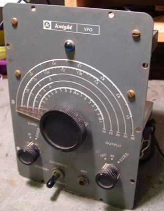
This is the front of the KnightKit
V44 VFO right out of the box with the case removed. I was happy to see that
all the knobs were there and they matched. Over the years, Knight Kit used
many types of knobs during the production run |
|
|
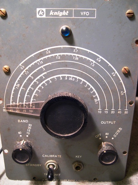
This is a close up of the front
panel. As you can see, it is veery dirty. Also the screw have rust on them.
These will be replaced of course. I have yet to power up the unit. The plan
is to partially "de-kit" the unit. I will remove the front panel
and clean it carefully. |
|
|
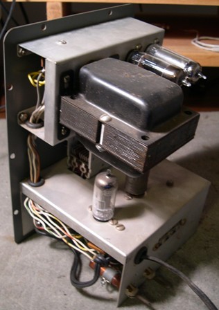
Here is a look at the back.
What is unique about this VFO is that is has a power supply built in. Not
a lot of VFOs in the 50s and 60s had built in power supplies. The engineers
did it right here, place the heat producing power supply above the actual
VFO circuitry. I will replace the electrolytic capacitor in the power supply
before powering up the unit. The rectifier tube is a 6X4 and has a choke
input. An OA2 provides voltage regulation |
|
|
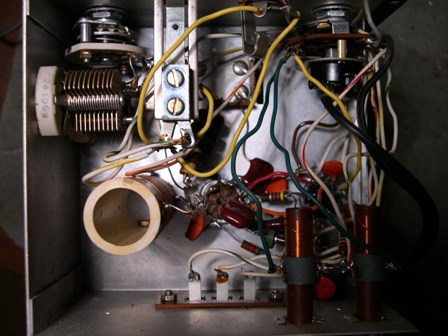
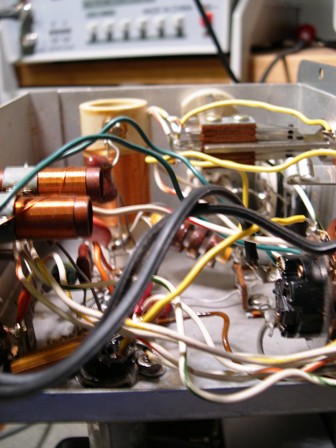
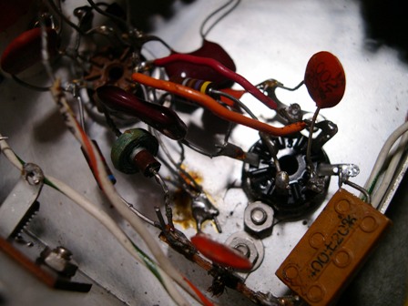
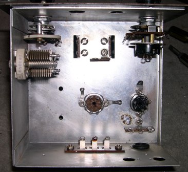
Here is the "guts"
of the VFO. All the parts are there. It looks pretty good, but I am planning
to shorten up some leads around the tubes. Also, the builder made some modifications
during building. What you say? Apparently, instead of using ground lugs,
the builder soldered leads to the case. Not a big deal, but I am going to
make sure it is built as per the instructions. |
|
|
Another shot of the "guts"
of the VFO. The only thing I did when I opened the case was to cut off the
coax cable that would connect to the transmitter. The cable was broke and
being held on by the braid. |
|
|
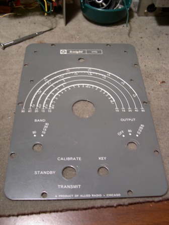
This is the front panel ofthe VFO cleaned up.
I used plain dishwashing liquid to wash it up. It came out pretty good.
Not perfect, but good. |
|
|
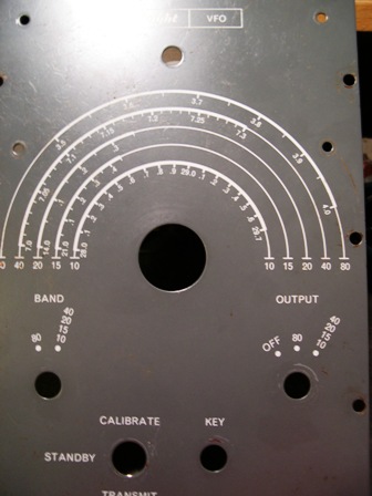
Another view of the front panel. You can see some scratches.
I have scanned the front panel and am working on a printed
version of the front panel. Using PhotoShop. Getting rid of all the bad
scratches and dinks and dents in the front panel. The plan is to laminate
a good photo quality version of the front panel and then using it as an
overlay. If you want a copy of it, send me an email.
|
|
|
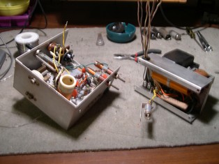
The VFO comes ouyt in two pieces, the oscillator
section and the power supply. |
|
|
Looks like this unit was put together by a
starting ham. Yes, of course it was. I keep marvelling how crappy the thing
looked inside. But, I have to remember, this was not a professional job
or even and experienced job. Therefore, I am taking it all the way apart.
Bad soslder joints, solder to the case (OK, but I am going to use the lugs
called for in the instructions) and some loose hardware. |
 |
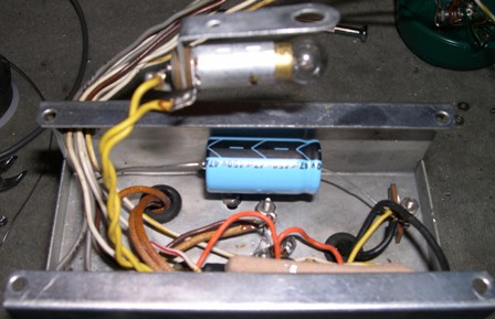
This is the guts of the power supply. I have
not looked that far into this piece, but I am going to replace the electroltic
capacitor. I have one on order from Mouser. |
|
|
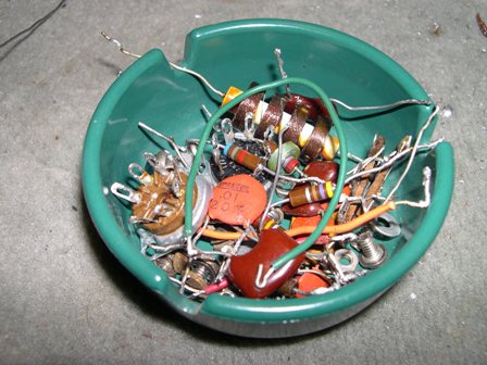
Parts from the vfo after a partial "de-kit."
11-26-09 |
|
|
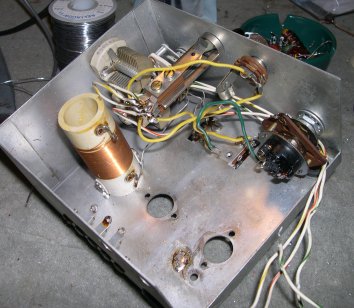
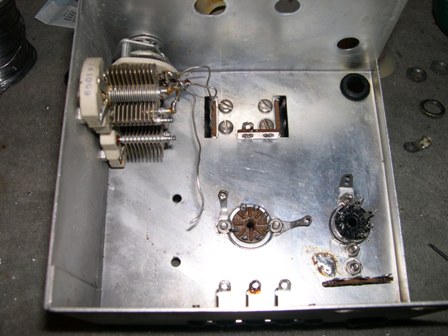
Underneath of the VFO Oscillator chasis after
most of the parts were removed. Some of the wiring will be rerouted as per
the instructions. 11-27-09 |
|
|
Clean VFO Oscilator chasis top side. I spent
quite a bit of time getting "gunk" off the unit and it is not
a perfect job to say the least. But it is a lot cleaner that what it was.
11-27-09 |
 |
I am starting to "re-kit" the VFO.
I decided to remove more parts to have more room to work. It was very easy
at this point to take out more of the parts. One of the things I noticed
when I took the unit apart is that the hardware was not tight. So, I am
make sure things are snug. 11-28-09 |
|
|
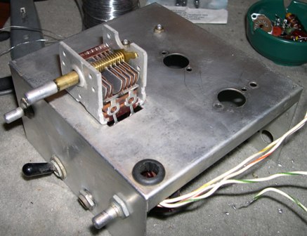
Hey, I am learning here! I finally had all
of the parts out of the chasis now. I had to. I could not get the switches
line up on the front panel. The power switch was OK, but not the band switch.
Rats. So, it had to all come out and get cleaned up, including the trimmer
capacitors. Now, I think I am ready to start putting more parts back in.
I think that it would behoove those who try a project like this...restoring
a kit...to realize they have to take it all apart. This kit was not done
well as I have said earlier. The builder of these kits were teenagers at
the time and beginning hams who had no experience. So, with that said, "Buyer
Beware." You might get a "pig in a poke." I did not...I think
this unit is going to work grand when it is done. 11-28-09 |
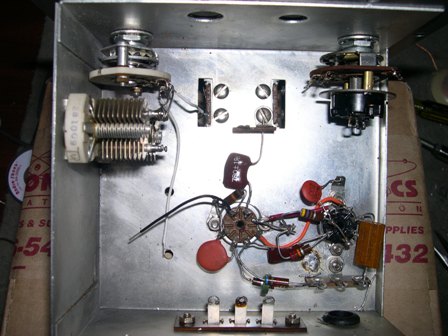 |
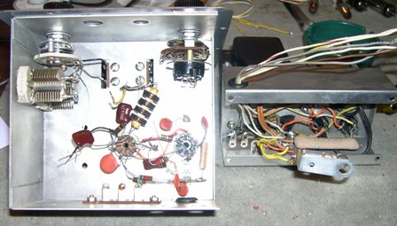
This is what it looks like as I am re-kitting
the VFO. Using the old parts is somewhat difficult. The choke in the lower
part of the picture under the resistor was not working. To high of resistance.
I had cleaned up the choke and found that I had unsolder the wires of the
choke itself. I got that repaird (barely) and now it shows a low resistance
like it should. 11-28-09 (around Midnight) |
|
|
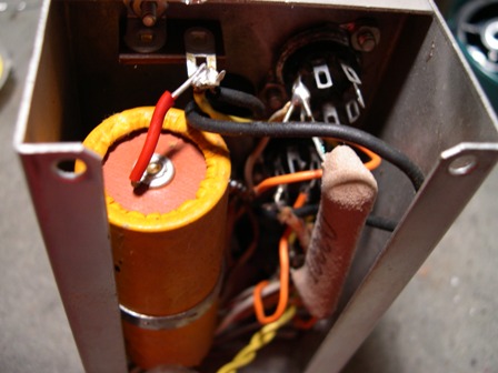
Put a new electrolytic capacitor in the power supply.
The part is much smaller than the stock capacitor. Simple choke input
power supply using a 6X4. No bleeder resistor. The large resistor in the
front of the picture is the dropping resistor the 0A2 regulator tube.
I like tubes that glow purple.
|
|
|
Now it is time to put the power supply and
the oscillator together. Wires need to be run for filament, B+, AC, and
control. The V44 is a nice FVO from the stand point that it has its own
power supply...something that was not common in the 50s and 60s. The engineers
at KnightKit also put the power supply above the oscillator this keeping
the lower part of the VFO cooler. |
| |
|
| |
|